18-1 Current, and Batteries
In Chapters 16 and 17, our main focus was on static charge. We turn now to look at
situations involving flowing charge. Controlling that flow is the basis of many electric circuits.
Current is the rate at which charge flows. The symbol we use for current is I:
(Equation 18.1: Current, the rate of flow of charge)
The unit for current is the ampere (A). 1 A = 1 C/s.
The direction of current is the direction positive charges flow, a definition adopted by
Benjamin Franklin before it was determined that in most cases the charges that flow in a circuit
are electrons (negative charges). However, in a circuit positive charge flowing in one direction is
equivalent to an equal amount of negative charge flowing at the same rate in the opposite
direction.
In general, circuits in which charge flows in one direction are direct current (DC)
circuits. In alternating current (AC) circuits (such as those in your house) the current direction
continually reverses direction. Despite this difference, many of the concepts addressed in this
chapter apply to both DC and AC circuits.
Batteries
What causes charge to flow? In general, charge flows from one point to another when
there is a potential difference between the points. A battery can create such a potential difference.
This potential difference gives rise to an electric field within the wires and the other elements of a
circuit. Charged objects, such as electrons, in this field experience a force which can cause them
to move. Note that, previously, we discussed how the electric field within a conductor is zero
when the conductor is in static equilibrium. In this case, when we have a non-zero electric field
within the conductor, we have more of a dynamic equilibrium – a steady flow of charge may be
established as the charges respond to the non-zero field.
A battery can be thought of as an electron manufacturing and recycling system. It does
not create electrons. Rather, a chemical reaction that liberates electrons takes place at the negative
terminal of the battery. If the battery is connected in a circuit the electrons travel through the
circuit, giving up energy along the way (such as to a light bulb a toaster element), to the positive
terminal of the battery. At the positive terminal a different chemical reaction takes place that
recycles the electrons, binding them into waste products. It is also important that charge flows
within the battery between the positive and negative terminals – this charge is often positive ions.
Consider a lead-acid car battery as an example. The battery’s positive terminal is made
from lead dioxide, the negative terminal from lead, and both terminals are immersed in a solution
of dilute sulphuric acid. The sulphuric acid contains water molecules as well as ions of and
. The chemical reaction that takes place at the negative terminal liberates two electrons:
.
After traveling through the circuit, these electrons are recycled at the positive terminal:
.
Chapter 18 – DC (Direct Current) Circuits Page 18 - 2
To keep the system going, there must be a net flow of positive ions from the negative
terminal to the positive terminal.
As in any manufacturing process, there are raw materials (the electrodes, and the acid
solution), there is a product (the electrons), and there are waste products (the and water).
A battery runs out when its raw materials are used up, or when enough waste products build up to
inhibit the reactions. In a rechargeable battery, the battery is recharged by running the chemical
reactions in the opposite direction, re-creating the electrodes and removing waste products.
Fuel cells use a similar process as batteries but, whereas a battery is a closed system in
which its raw materials and waste products are sealed in a container, in a fuel cell everything is
open so that raw materials can be continually fed into the system and waste products removed. A
number of manufacturers are researching ways to run portable electronic devices, such as laptops
and cell phones, from fuel cells instead of from batteries. The advantage offered by the fuel cell is
that you could run the device for significantly longer than you could run it off a battery. Also,
instead of plugging the device into an electrical outlet for a few hours to re-charge it, you could
just take a few seconds to top it up with, say, methanol, and the device would be good to go again.
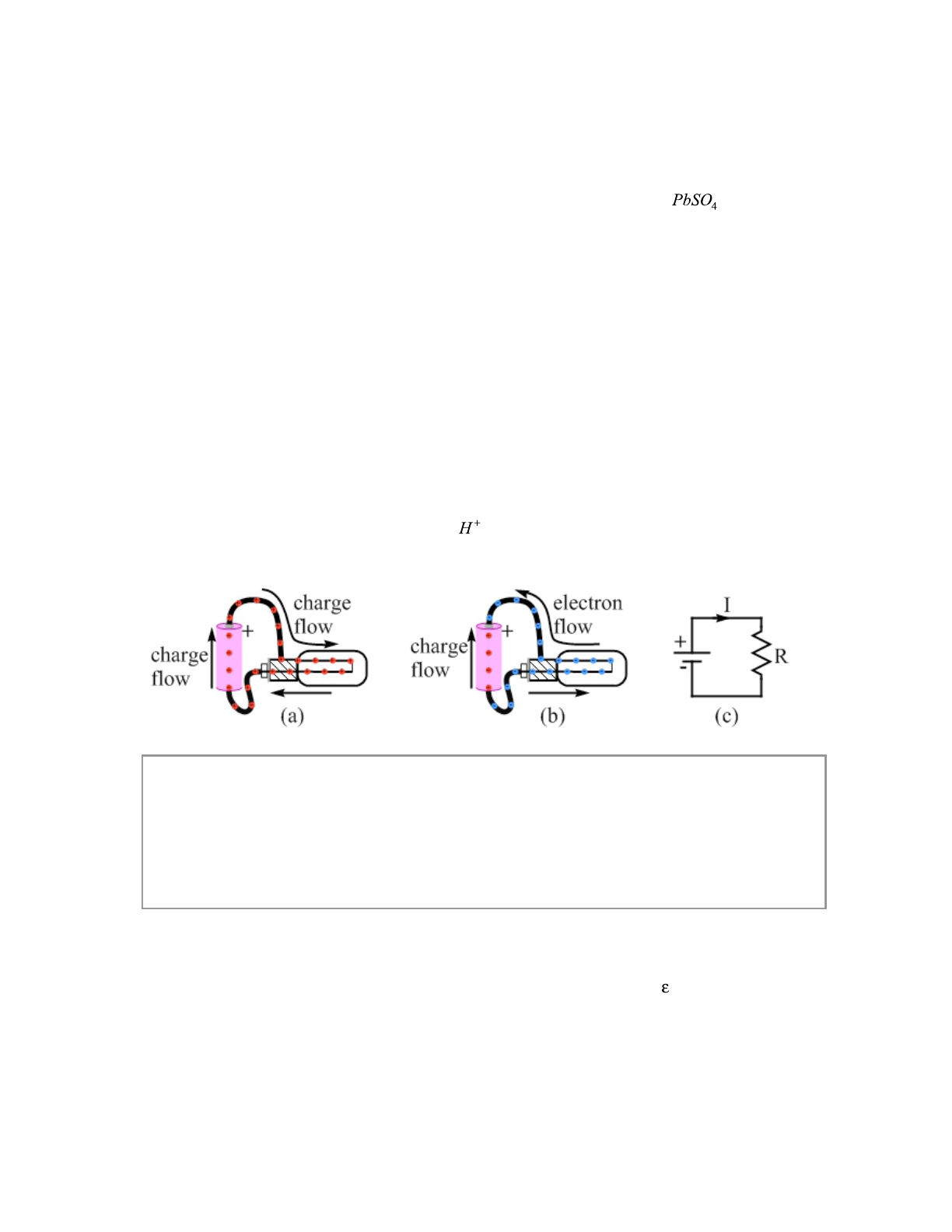
Figure 18.1 has three views of a circuit involving a battery, two wires, and a light bulb.
Figure 18.1(a) shows conventional current, where the charges flowing are positive. Figure 18.1(b)
shows the actual situation, showing that the charges flowing through the wires and the light-bulb
filament are actually electrons, while positive ions flow within the battery itself. The two
situations look different, but the light bulb would be equally bright in either case. Figure 18.1(c)
shows the circuit diagram. The current I is in the direction of conventional current.
Every battery has an associated potential difference: for instance, a 9-volt battery
provides a potential difference of around 9 volts. This is the potential difference between the
battery terminals when there is no current, and is known as the battery emf, (emf stands for
electromotive force, and you say emf as it is spelled, e-m-f).
Related End-of-Chapter Exercises: 13, 15.
Essential Question 18.1: Which is closer to the truth – a battery is a source of constant potential
difference, or a battery is a source of constant current? Explain.
Chapter 18 – DC (Direct Current) Circuits Page 18 - 3
Figure 18.1: Three views of a battery-powered circuit. Figure (a) shows conventional current, in
which the charge that flows is always positive. Figure (b) shows the actual situation, in which
electrons flow through the circuit and positive ions flow within the battery. Figure (c) shows a
circuit diagram for this circuit. R stands for resistor, which we cover in the next section. The
arrow under the I shows the direction of the conventional current. The two parallel lines, the
shorter one marked with a – and the longer one with a plus, represent the standard symbol for a
battery in a circuit diagram. The + is the positive terminal, and the – is the negative terminal.
